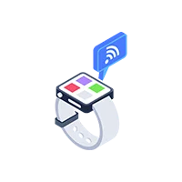
We wrote a program on ESP32 for an electrode position paint system and also developed a mobile application for Android and iOS to control, monitor, and analyze the data collected during the painting process.
A. DATA LOGGER:
-
We make a data logger and an electrodepositing paint system with small voltage, temperature, and DC current sensors that are powered by batteries and are connected to Android and iOS app.
-
Logger can record the summary data every second and collect the data in flash after every 5 minutes.
-
Data will be send it to the mobile app over BLE for post-processing, report & chart generation if it is armed by the user
Program For Firmware:
-
Create a Method to save all run data in one file.
-
It allows the temperature sensor to acclimate from ambient (~20 C) to the temperature of the paint bath, which is generally > 30 C.
-
Battery Charging Mode: When the Unit is placed on its’ charging pad the LiPO battery management chip handle charging. As per the business logic, at this moment the BLE is not connected and the unit will not arm during this time.
-
Wake up from Deep Sleep & Connect to BLE Central: When the logger is removed from its’ case and ambient light falls on the Charging unit is awakening from sleep, it will connect with a BLE Central device to set the parameters for the run and also Arm the unit.
-
Logging: Logging is triggered by a user-selectable voltage set point or loss of ambient light. During the painting process, the measured temperatures go below the set point, but our system has a Time Zone correction to determine when to stop the charging.
-
After a Logging event: The unit looks for a BLE Central to connect to. Once this happens then the run data file opens. Post-processing occurs (calibration, scaling, etc) details of the run display on the screen of the BLE Central device.
B. BLE App:
-
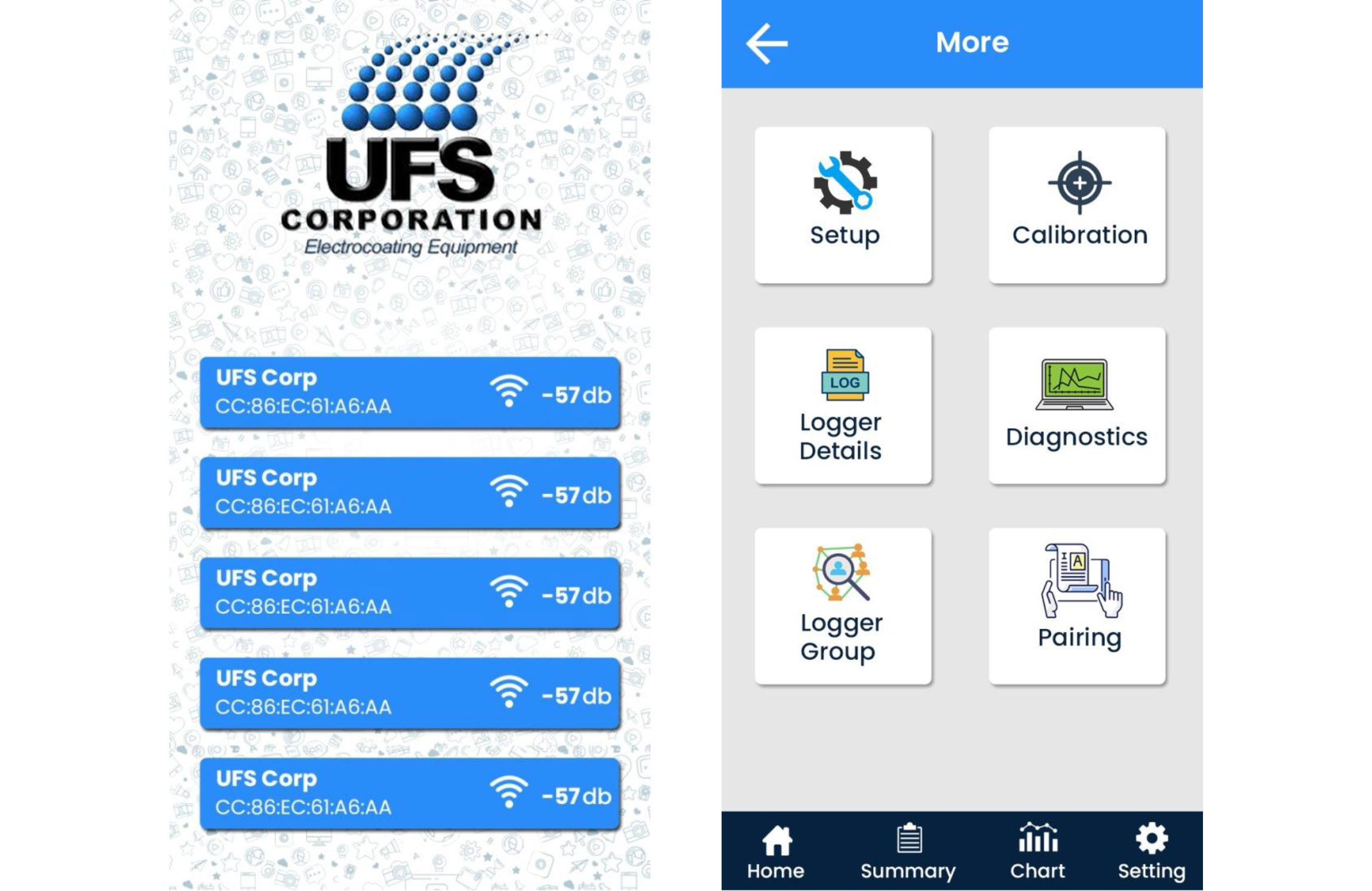
For the BLE app, we have created native Android & iOS Applications, named UFS Corporation.
-
For the combined results of up to 7 loggers (i.e. peripherals) together with a BLE Central (i.e. Phone), we add the following features in the application:
-
To activate the device to read its parameters, we added the toggle button to set on ambient light or voltage trigger.
-
After triggering the board, a blue LED starts flashing where the data summary in the Run data summary page of the App is shown.
-
Till this point, you can see the data of the sensors and also set the threshold for voltage trigger, Interzone timeout, etc.
-
To start the logging, we added a button to the arm and then green LED flashed indicating the logging has started.
-
The data logger puts the data in flash every 5 minutes and sends it to the BLE app to make the file.
-
In case the logging doesn’t stop the logger overwrites the data and sends it to the BLE app to append that data.
-
If the logging stops in between or the device is unarmed in between, the logger saves the collected data.
-
The app saves the Summary Report to a local Network, to an attached Storage device or to a Cloud provider.
-
The app displays 300 seconds worth of data on a small phone as well asdirect the chart to a local printer.
-
App has the ability to upgrade firmware OTA
-
After unarming the blue LED starts to flash.
-
If the battery is not low, then the Blue LED starts to flash indicating the BLE radio is On (acting as a peripheral).
-
Once a BLE Central is able to connect the Blue LED turns solid.
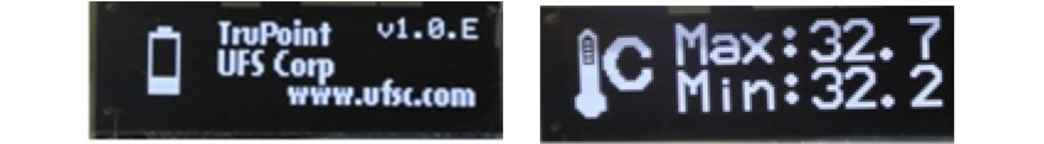
C. OLED Screens:
As requested by clients, we use existing icons to reduce the use of English language text for
- DC V max
- AC V max
- Temperature - low &. High
- V
- Create a new # Coulombs icon similar to others.
- Create a new DC A Peak con using DC V and replace ‘V’ with ‘A’.
We also provide a diagnostic routine; when μP pin is pulled Low, a diagnostic routine is started and results display on the OLED. Diagnostic Routine consists of
-
Times unit has been awakened
-
minutes in On state
-
data runs
-
Of times of logging termination due to low battery V
-
Any current errors
-
Error log history
-
Historical Max Temperature measured: Liquid/Air; Ware,& PCB.
-
Historical Max DC V
-
Historical Max AC V
-
Historical Max DC Current Historical Max # Coulombs
-
Historical Max of Total time > 8 V
-
Historical Max of μP die temperature
-
Max data run duration
-
Tally of a number of minute’s battery was being charged.
-
Tally of Total time > 8 accumulated for all data runs
-
Technical issues not resolved
-
Plug to keep paint off charging contacts.
After finishing a run, the unit activates BLE and sends the raw data (in the form of a CSV file) to "post processing," which includes calibration, scaling, report formatting, saving, retrieving, and comparing to previous data runs.
Analog inputs are calibrated on a regular basis, and calibration files are saved in RAM using the BLE app.
The temperature is noted as an integer, but displays in the BLE App as a decimal point as app divides the integer by 10 to produce a decimal point.
The calibration coefficient is calculated and saved within the module.
The App is able to aggregate the data from this cohort to produce a single file that is aligned by the data and timestamp.
D. Hardware Summary:
-
Silicon Labs PN #BGM220PC22HNA FCC approved Module
-
Small footprint so use 2 PCBs with a battery in between the boards
-
Pogo pins type charging method with a ~500 mAHrLiPo single cell battery
-
IP-67 3D printed case with clear cover
-
Phototransistor to detect ambient light
-
RGB LED to indicate: low battery/charging; BLE available/connected; color code when armed
-
32 x 128 B&W SPI OLED (Crystalfontz PN CFAL12832D-B)*
-
~2 cm^2 metal plate that is grounded through magnet - a paint film will form on its’ exterior.
-
Reset button
-
Internal pad when shorted to GND will start diagnostic routine.
-
12 Bit ADC with 0 - 3V3 input range
-
I2C display CFAL12832C0-01B-W. OLED display may be deleted after beta testing if BLE connection renders it redundant.

 Mean Stack Development
 Vue JS Development
 Javascript Development
 React JS Development
 Angular JS Development
 Next JS development
 Java Development
 Python Development
 Django Development
 Cherrypy Development
 C# Development
 ASP.NET Development
 NodeJS Development
 Laravel Development
 CodeIgniter Development
 Zend Development
 Ruby on Rails Development
 CakePHP Development
 PHP Website Development
 Symfony Development
 Drupal Development
 Joomla Development
 Wordpress Development
 .NET Nuke Development
 Kentico
 Umbraco
 .NET MAUI Development
 Xamarin Application Development
 iOS Application Development
 Android Application Development
 Android Wear App Development
 Ionic Development
 Universal Windows Platform (UWP)
 Kotlin Application Development
 Swift Application Development
 Flutter Application Development
 PWA Application Development
 Offshore Software Development
 Custom Application Development
 Front-End Development
 Full Stack Development
 AI & Machine Learning
 Custom CRM Solutions
 Flask Software Development
 Electron JS Development
 ChatGPT Development
 Magento Development
 Magento 2.0 Development
 Magento Enterprise
 Shopping Cart Development
 Prestashop Development
 Shopify Development
 Open Cart Development
 WooCommerce Development
 BigCommerce Development
 NopCommerce Development
 Virto Commerce Development
 AspDotNetStorefront Development
 RaspBerry Pi
 Firmware Software Development
 ESP 32 Software Development
 Embedded Development
 Internet of Things
 Nordic Development
 .NET Application Development
 Microsoft Dynamics CRM
 VB .NET Development
 Sharepoint Migration
 ASP.NET Core Development
 ASP.NET MVC Development
 AJAX Development
 Agile Development
 Microsoft Bot
 Microsoft Blazor
 Microsoft Azure Cognitive
 HTML 5
 UI/UX Design
 Graphic Design
 Adobe Photoshop
 XML Application Development
 Cloud Computing Solutions
 Azure Cloud App Development
 AWS Development
 Google Cloud Development
 SQL Programming Development
 MySQL Development
 MongoDB Development
 Big Data
 Robotic Process Automation
 Social Media Marketing
 Search Engine Optimization
 QA Testing
 Software Testing
 Software Security
 Maintenance And Support
 I.T. Consulting Services
 Business Intelligence
 YII Development
 Data Analysis
 Alexa Skills Development
 On Demand App for Mobile repairing services
 On Demand App for Car Service Booking
 On Demand App for Cleaning Services
 On Demand App for Pharmacy
 On Demand Dedicated Developers